
Ex Scientia Tridens
This section covers the gadgets I made for Ex Scientia Tridens.
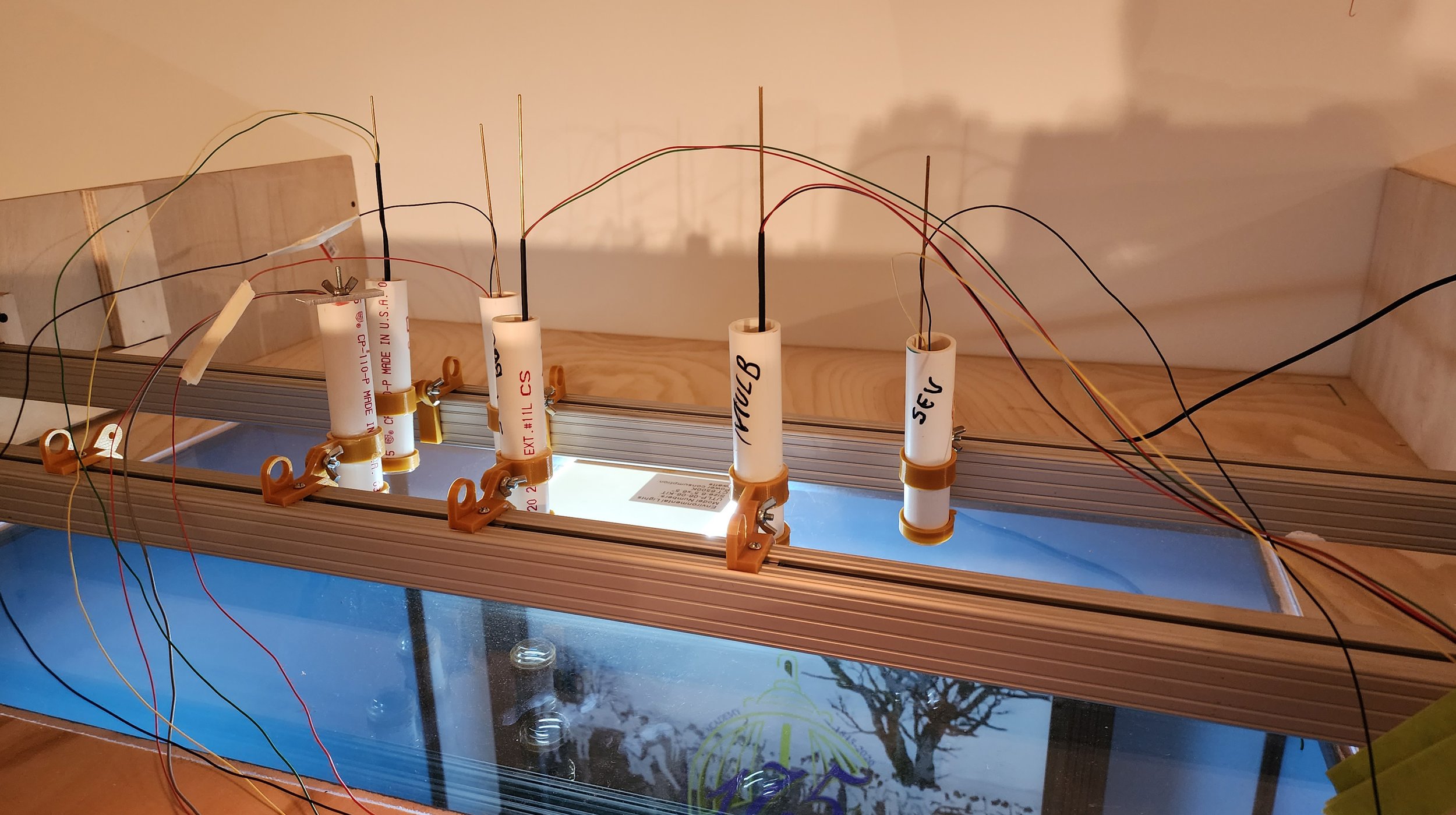
I needed pin spots for the Diorama display, but the smallest spots I could find cast a circle of light about a foot in diameter over 36 inches. I needed more like 3 inches in diameter over the same distance. So I bought some children's plastic magnifying glasses for lenses and used some PVC pipe for the barrels. The orange/gold bits that you see were made on my 3D printer.

Some oddly shaped things require oddly shaped mounts. Here you see a dumbell used by the midshipmen in gym class. Go to the next slide to see the mounts.
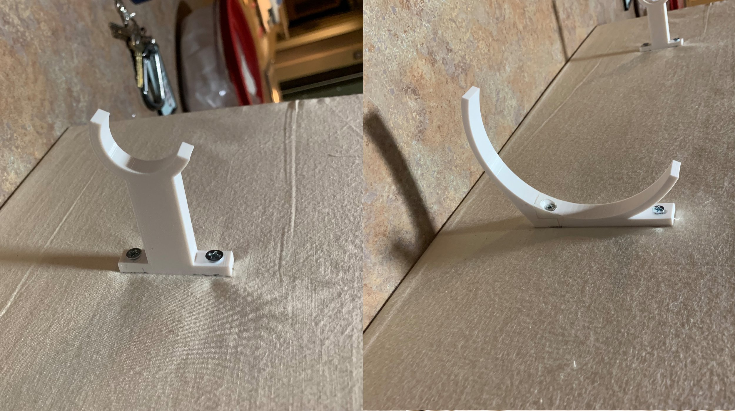
I printed these on my 3D printer. Much easier than forming the mounts out of brass or plexi.
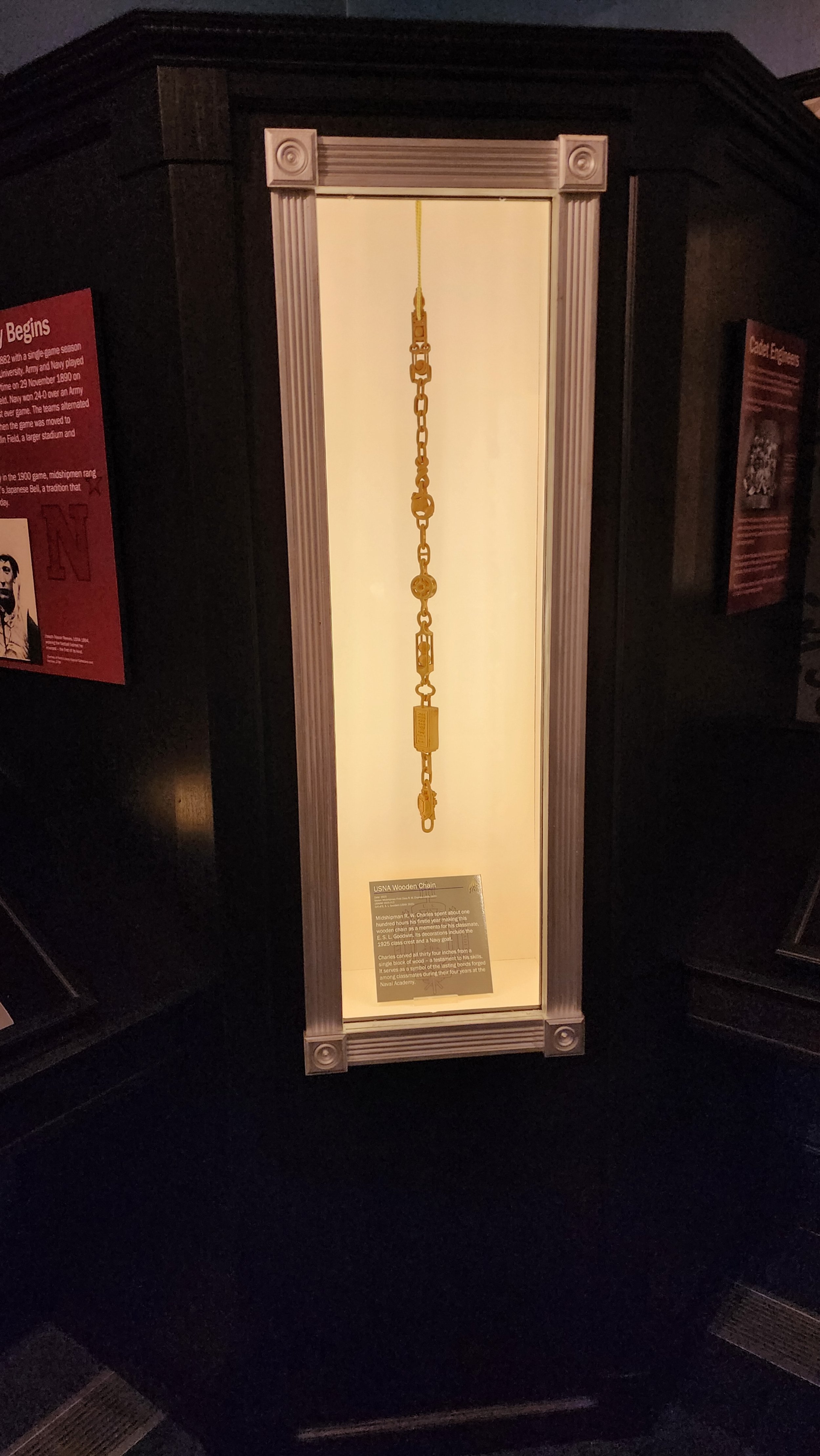
We had a chain that was carved out of a single piece of wood. It had interesting features on both sides, so we decided to make it spin. Next slide.
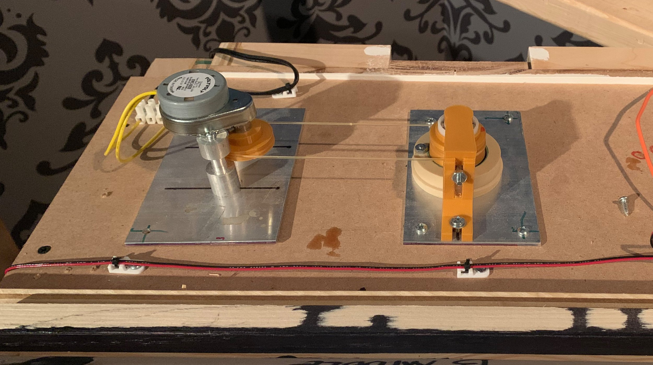
I made this little spin mechanism out of a microwave platter spinner. It is constructed with a pulley (rather than direct drive) so that you can change the motor without disturbing the artifact. The orange/gold bits are from the 3D printer.

Here is the video cubby from the exhibit. You can see the particular section that is illuminated as that feature is discussed in the video. Next slide.

The map (a reproduction, of course) is mounted to a sheet of MDF. Carefully placed cutouts are provided and each is compartmented from the others and provided with a VERY bright LED puck. Next slide.
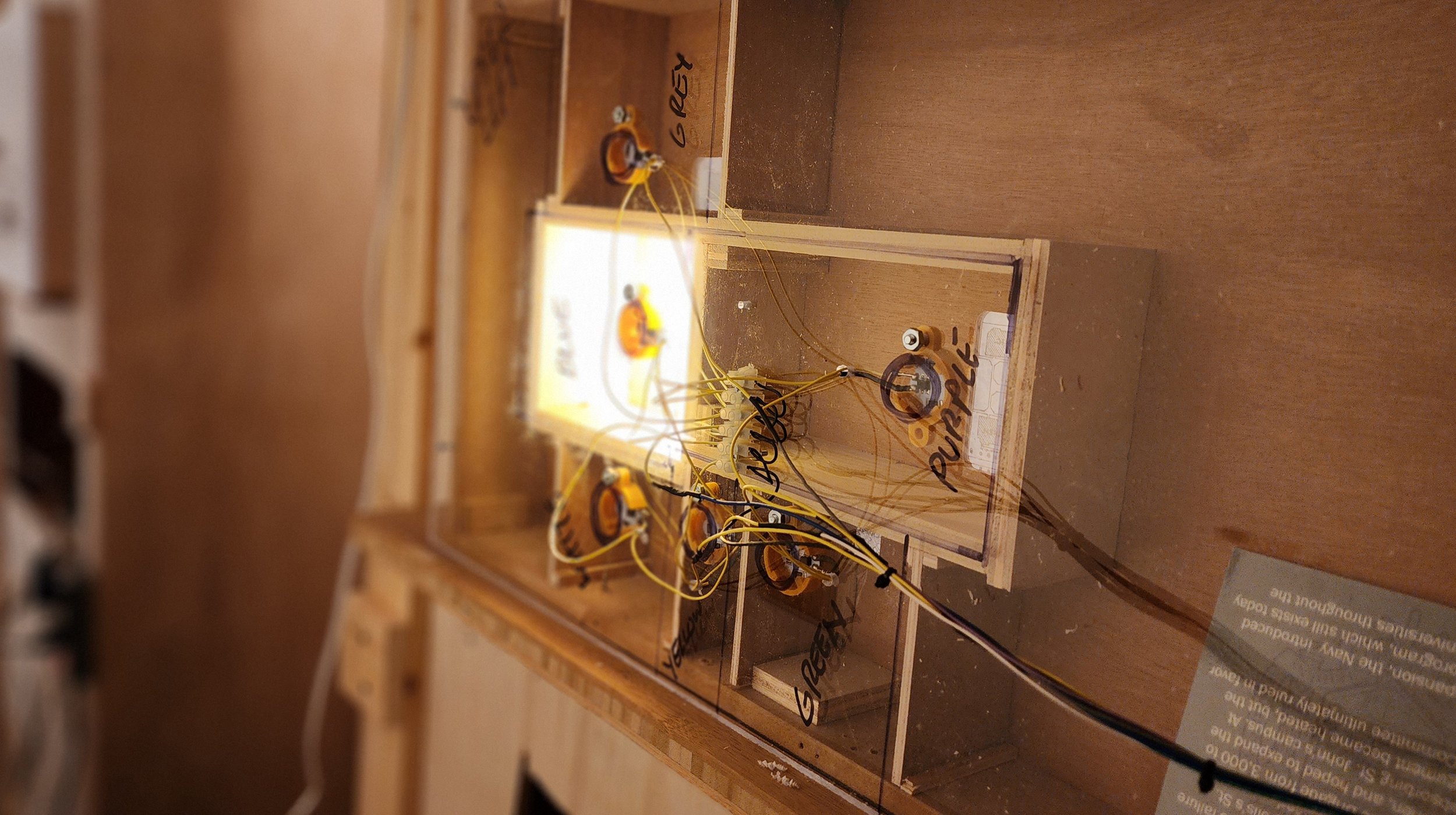
This shows a particular compartment while it is illuminated. Although the cutouts are not detectable while dark, they are clearly visible when illuminated.
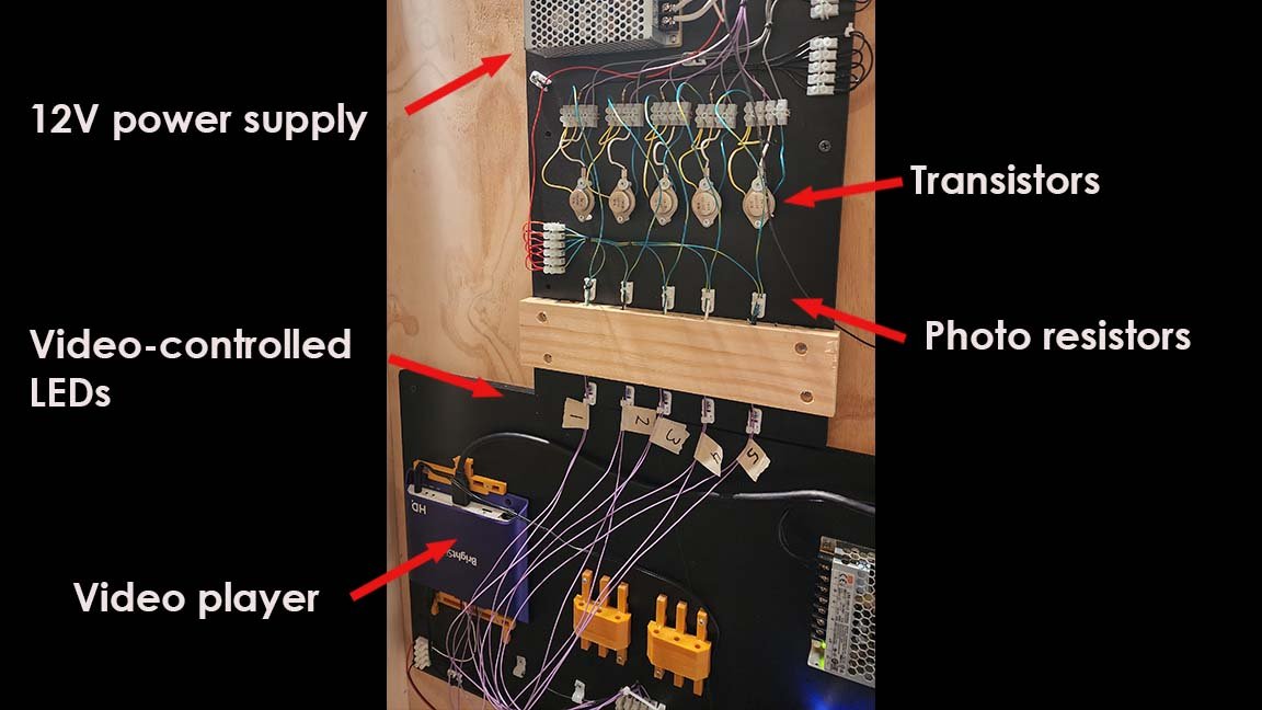
The lights behind the maps are controlled by the circuit seen here. The video player turns LEDs on and off in sinc with the video. These LEDs are placed into holes in the board you see. In the other end of each hole, photo-resistors are placed. When the player turns on an LED, it gates the transistor and turns on the map light. Basically, it's a home-made opto isolator.
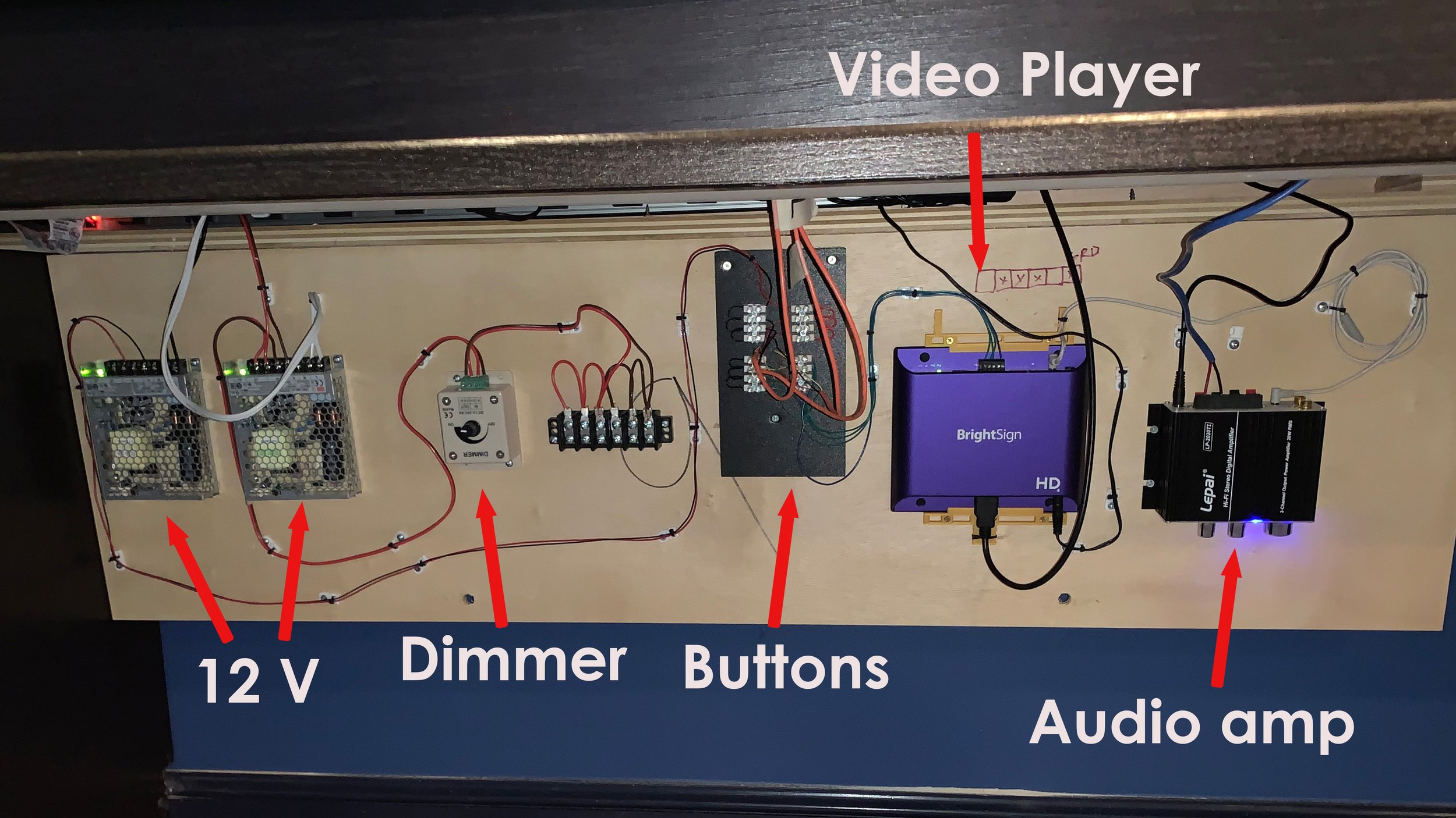
This is a picture of the under-panel drop downs in the reader rails. Very basic set up: 12V power supply runs through a dimmer that controls the case lights. No touch buttons (next slide) control the video player, and the audio amp powers the speakers on the reader rail panel.
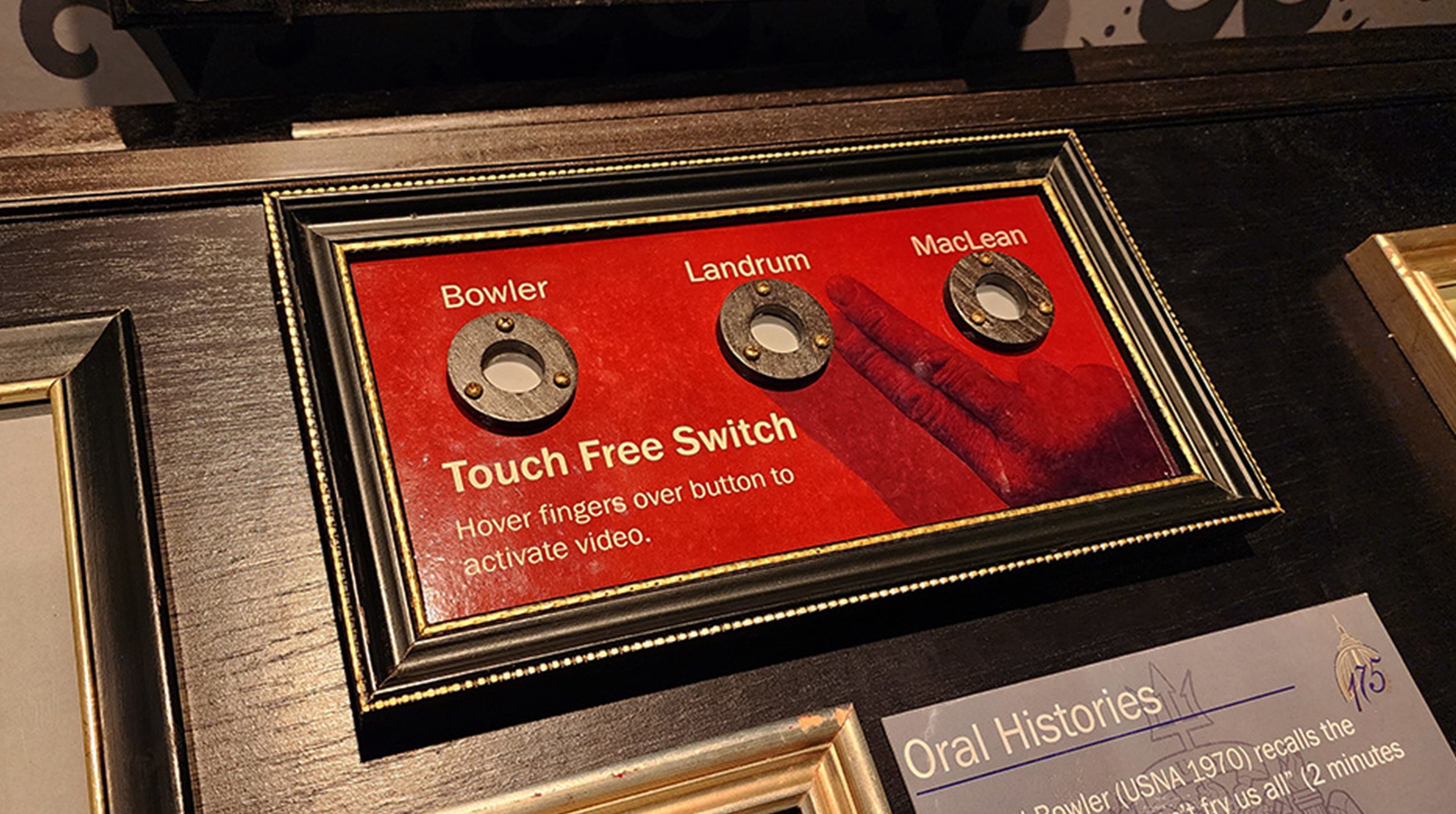
I forgot to take a picture of the gadget that runs these buttons before I installed them, so you'll just have to trust me. Basically, there is a photo-sensitive relay at the bottom of a tube that is aligned with the openings you see above. The spotlight above holds these relays shut, and when a shadow passes in front of the opening, the relay drops out and the video is activated. Works pretty good.
